
.(Independent multitasking LEDs blink using Arduino FreeRTOS, and send the data wirelessly using bluetooth module HC-05. :) )
http://ift.tt/2b4YNBe.
the code is same as here
.(Independent multitasking LEDs blink using Arduino FreeRTOS, and send the data wirelessly using bluetooth module HC-05. :) )
http://ift.tt/2b4YNBe.
the code is same as here

int n = 0;

// define two tasks for Blink & AnalogRead
void TaskBlink( void *pvParameters );
void TaskBlink2( void *pvParameters );
void TaskBlink3( void *pvParameters );
void TaskBlink4( void *pvParameters );
void TaskTadaa( void *pvParameters );

// the setup function runs once when you press reset or power the board
void setup() {
   // initialize serial communication at 9600 bits per second:
  Serial.begin(9600);

  // Now set up two tasks to run independently.
  xTaskCreate(
    TaskBlink
    ,  (const portCHAR *)"Blink"   // A name just for humans
    ,  128  // Stack size
    ,  NULL
    ,  2  // priority
    ,  NULL );
  xTaskCreate(TaskBlink2,(const portCHAR *)"Blink2",128, NULL,2,NULL );
  xTaskCreate(TaskBlink3,(const portCHAR *)"Blink3",128, NULL,2,NULL );
  xTaskCreate(TaskBlink4,(const portCHAR *)"Blink4",128, NULL,2,NULL );

  xTaskCreate(
    TaskTadaa
    ,  (const portCHAR *) "Tadaa"
    ,  128 // This stack size can be checked & adjusted by reading Highwater
    ,  NULL
    ,  1  // priority
    ,  NULL );

  // Now the task scheduler, which takes over control of scheduling individual tasks, is automatically started.
}

void loop()
{
  // Empty. Things are done in Tasks.
}

/*--------------------------------------------------*/
/*---------------------- Tasks ---------------------*/
/*--------------------------------------------------*/

void TaskBlink(void *pvParameters)  // This is a task.
{
  (void) pvParameters;

  // initialize digital pin 13 as an output.
  pinMode(13, OUTPUT);

  for (;;) // A Task shall never return or exit.
  {
    digitalWrite(13, HIGH);   // turn the LED on (HIGH is the voltage level)
    Serial.println("LED 13 Nyala");
    vTaskDelay( 1000 / portTICK_PERIOD_MS ); // wait for one second
    digitalWrite(13, LOW);    // turn the LED off by making the voltage LOW
    Serial.println("LED 13 Padam");
    vTaskDelay( 1000 / portTICK_PERIOD_MS ); // wait for one second
  }
}
void TaskBlink2(void *pvParameters){
  (void) pvParameters;
  pinMode(2, OUTPUT);
  for (;;) {
    digitalWrite(2, HIGH); vTaskDelay( 2000 / portTICK_PERIOD_MS );Serial.println("LED 2 Nyala");
    digitalWrite(2, LOW);  vTaskDelay( 2000 / portTICK_PERIOD_MS );Serial.println("LED 2 Padam");
  }
}

void TaskBlink3(void *pvParameters){
  (void) pvParameters;
  pinMode(3, OUTPUT);
  for (;;) {
    digitalWrite(3, HIGH); vTaskDelay( 500 / portTICK_PERIOD_MS );Serial.println("LED 3 Nyala");
    digitalWrite(3, LOW);  vTaskDelay( 1500 / portTICK_PERIOD_MS );Serial.println("LED 3 Padam");
  }
}

void TaskBlink4(void *pvParameters){
  (void) pvParameters;
  pinMode(4, OUTPUT);
  for (;;) {
    digitalWrite(4, HIGH); vTaskDelay( 500 / portTICK_PERIOD_MS );Serial.println("LED 4 Nyala");
    digitalWrite(4, LOW);  vTaskDelay( 250 / portTICK_PERIOD_MS );Serial.println("LED 4 Padam");
  }
}

void TaskTadaa(void *pvParameters)  // This is a task.
{
  (void) pvParameters;
  for (;;)
  {
    // read the input on analog pin 0:
    n++;
    if (n>100){n = 0;}
    // print out the value you read:
    Serial.print("Tadaa...");
    Serial.println(n);
    vTaskDelay(2000/portTICK_PERIOD_MS);// 2 second delay
    // one tick delay (15ms) in between reads for stability
  }
}

(Real Time Operating System).
Multi Tasking on Arduino Nano.
Led Blink and Serial Communication
http://ift.tt/2b30d2l.
#include
int n = 0;

// define two tasks for Blink & AnalogRead
void TaskBlink( void *pvParameters );
void TaskTadaa( void *pvParameters );

// the setup function runs once when you press reset or power the board
void setup() {


  // Now set up two tasks to run independently.
  xTaskCreate(
    TaskBlink
    ,  (const portCHAR *)"Blink"   // A name just for humans
    ,  128  // Stack size
    ,  NULL
    ,  2  // priority
    ,  NULL );

  xTaskCreate(
    TaskTadaa
    ,  (const portCHAR *) "Tadaa"
    ,  128 // This stack size can be checked & adjusted by reading Highwater
    ,  NULL
    ,  1  // priority
    ,  NULL );

  // Now the task scheduler, which takes over control of scheduling individual tasks, is automatically started.
}

void loop()
{
  // Empty. Things are done in Tasks.
}

/*--------------------------------------------------*/
/*---------------------- Tasks ---------------------*/
/*--------------------------------------------------*/

void TaskBlink(void *pvParameters)  // This is a task.
{
  (void) pvParameters;

  // initialize digital pin 13 as an output.
  pinMode(13, OUTPUT);

  for (;;) // A Task shall never return or exit.
  {
    digitalWrite(13, HIGH);   // turn the LED on (HIGH is the voltage level)
    vTaskDelay( 1000 / portTICK_PERIOD_MS ); // wait for one second
    digitalWrite(13, LOW);    // turn the LED off by making the voltage LOW
    vTaskDelay( 1000 / portTICK_PERIOD_MS ); // wait for one second
  }
}

void TaskTadaa(void *pvParameters)  // This is a task.
{
  (void) pvParameters;

  // initialize serial communication at 9600 bits per second:
  Serial.begin(9600);

  for (;;)
  {
    // read the input on analog pin 0:
    n++;
    if (n>100){n = 0;}
    // print out the value you read:
    Serial.print("Tadaa...");
    Serial.println(n);
    vTaskDelay(2000/portTICK_PERIOD_MS);// 2 second delay
    // one tick delay (15ms) in between reads for stability
  }
}


menu.cpu=Processor
menu.clock=Clock
attiny.name=ATtiny
attiny.bootloader.tool=arduino:avrdude
attiny.bootloader.unlock_bits=0xff
attiny.bootloader.lock_bits=0xff
attiny.build.core=arduino:arduino
attiny.build.board=attiny
attiny.upload.tool=arduino:avrdude
#attiny.upload.tool=usbasp

#################################################
attiny.menu.cpu.attiny13=ATtiny13
attiny.menu.cpu.attiny13.upload.maximum_size=1024
attiny.menu.cpu.attiny13.build.mcu=attiny13
attiny.menu.cpu.attiny13.build.variant=core13

attiny.menu.clock.internal96=9.6MHz (internal)
attiny.menu.clock.internal96.bootloader.low_fuses=0x7A
attiny.menu.clock.internal96.bootloader.high_fuses=0xff
attiny.menu.clock.internal96.build.f_cpu=9600000L

################################################

attiny.menu.clock.internal48=4.8MHz (internal)
attiny.menu.clock.internal48.bootloader.low_fuses=0x79
attiny.menu.clock.internal48.bootloader.high_fuses=0xff
attiny.menu.clock.internal48.build.f_cpu=4800000L
################################################
usbasp.name=USBasp
usbasp.communication=usb
usbasp.protocol=usbasp
usbasp.program.protocol=usbasp
usbasp.program.tool=avrdude
usbasp.program.extra_params=-Pusb -B4
usbasp.name=USBaspN
usbasp.communication=usb
usbasp.protocol=usbasp
usbasp.program.protocol=usbasp
usbasp.program.tool=avrdude
usbasp.program.extra_params=-Pusb -B4
const int ledPin =  1;      // the number of the LED pin
int ledState = LOW;             // ledState used to set the LED
unsigned long previousMillis = 0;        // will store last time LED was updated
const long interval = 1000;           // interval at which to blink (milliseconds)
void setup() {
  pinMode(ledPin, OUTPUT);
}

void loop()
{
  unsigned long currentMillis = millis();
  if(currentMillis - previousMillis >= interval) {
    previousMillis = currentMillis;
    if (ledState == LOW)
      ledState = HIGH;
    else
      ledState = LOW;
    digitalWrite(ledPin, ledState);
  }
}


SoftwareSerial mySerial(8, 9); // RX, TX.
int t=1;
int i=1;
LiquidCrystal lcd(12, 11, 5, 4, 3, 2);//rs e d4 d5 d6 d7
String tulisan = "Tadaa..., heheh...., hihihi :)";
String info =":)";
void setup() {
pinMode(7,INPUT);
pinMode(6,OUTPUT);
pinMode(10,OUTPUT);
pinMode(13,OUTPUT);
lcd.begin(16, 2);
lcd.print(tulisan);
mySerial.begin(9600);
Serial.begin(9600);//port serial resmi
delay(1000);
}
void loop() {
//lcd.clear();
if (digitalRead(7)==1){
digitalWrite(10,HIGH);
}else{
digitalWrite(10,LOW);
}
if (mySerial.available()){
digitalWrite(13,HIGH);
while(mySerial.available()>0){
t=1;
lcd.clear();
tulisan=mySerial.readString();
mySerial.println(tulisan);
}
}
lcd.setCursor(1,0);
lcd.print(tulisan);
int l= tulisan.length()-12;
info ="P7=";
info+=digitalRead(7);
info+=",l=";
info+=tulisan.length();
info+=",a=";
info+=analogRead(A0);
lcd.setCursor(t,1);
lcd.print(info);
digitalWrite(13,LOW);
if (l>16){
lcd.scrollDisplayLeft();
t++;
if (t>=l){
t=1;
lcd.clear();
}
}
delay(1000);
}
//PWM: 3, 5, 6, 9, 10, and 11


SoftwareSerial mySerial(8, 9); // RX, TX.
int t=1;
int i=1;
LiquidCrystal lcd(12, 11, 5, 4, 3, 2);//rs e d4 d5 d6 d7
String tulisan = "Tadaa..., heheh...., hihihi :)";
String info =":)";
void setup() {
pinMode(7,INPUT);
pinMode(6,OUTPUT);
pinMode(10,OUTPUT);
pinMode(13,OUTPUT);
lcd.begin(16, 2);
lcd.print(tulisan);
mySerial.begin(9600);
delay(1000);
}
void loop() {
//lcd.clear();
if (digitalRead(7)==1){
digitalWrite(10,HIGH);
}else{
digitalWrite(10,LOW);
}
if (mySerial.available()){
digitalWrite(13,HIGH);
while(mySerial.available()>0){
tulisan=mySerial.readString();
mySerial.println(tulisan);
}
}
lcd.setCursor(1,0);
lcd.print(tulisan);
//scroll first row if text length's beyond 16
int l= tulisan.length()-12;
info ="P7=";
info+=digitalRead(7);
info+=",l=";
info+=tulisan.length();
lcd.setCursor(t,1);
lcd.print(info);
digitalWrite(13,LOW);
lcd.scrollDisplayLeft();
t++;
if (t>=l){
t=1;
lcd.clear();
}
delay(1000);
}
//PWM: 3, 5, 6, 9, 10, and 11
SoftwareSerial mySerial(8, 9); // RX, TX

LiquidCrystal lcd(12, 11, 5, 4, 3, 2);//rs e d4 d5 d6 d7
String tulisan = "Tadaa...";
String info =":)";
void setup() {
  pinMode(7,INPUT);
  pinMode(6,OUTPUT);
  pinMode(10,OUTPUT);
  pinMode(13,OUTPUT);
  lcd.begin(16, 2);
  lcd.print(tulisan);
  mySerial.begin(9600);
  delay(1000);
}


void loop() {
  if (digitalRead(7)==1){
    digitalWrite(10,HIGH);
  }else{
    digitalWrite(10,LOW);
  }
  if (mySerial.available()){
    lcd.clear();
    digitalWrite(13,HIGH);
    while(mySerial.available()>0){
      lcd.setCursor(0,0);
      tulisan=mySerial.readString();
      mySerial.println(tulisan);
      lcd.print(tulisan);
    }
  }

  //scLeft();
  //scRight();
  //scDef();
  info ="Pin7 = ";
  info+=digitalRead(7);

  lcd.setCursor(0,1);
  lcd.print(info);
  digitalWrite(13,LOW);
  delay(1000);
}

void scLeft(){
  for (int i = 0; i < tulisan.length(); i++) {
    lcd.scrollDisplayLeft();
    delay(150);
  }
}

void scRight(){
  for (int i = 0; i < (tulisan.length()+16); i++) {
    lcd.scrollDisplayRight();
    delay(150);
  }
}

void scDef(){
  for (int i = 0; i < 16; i++) {
    lcd.scrollDisplayLeft();
    delay(150);
  }
}
//PWM: 3, 5, 6, 9, 10, and 11
LiquidCrystal lcd(12, 11, 5, 4, 3, 2);//rs e d4 d5 d6 d7.
String tulisan = "Tadaa...";
void setup() {
lcd.begin(16, 2);
lcd.print(tulisan);
Serial.begin(9600);
delay(1000);
}
void loop() {
if (Serial.available()){
lcd.clear();
while(Serial.available()>0){
tulisan=Serial.readString();
lcd.print(tulisan);
}
}
// scroll 13 positions (string length) to the left
// to move it offscreen left:
for (int i = 0; i < tulisan.length(); i++) {
// scroll one position left:
lcd.scrollDisplayLeft();
// wait a bit:
delay(150);
}
// scroll 29 positions (string length + display length) to the right
// to move it offscreen right:
for (int i = 0; i < (tulisan.length()+16); i++) {
// scroll one position right:
lcd.scrollDisplayRight();
// wait a bit:
delay(150);
}
// scroll 16 positions (display length + string length) to the left
// to move it back to center:
for (int i = 0; i < 16; i++) {
// scroll one position left:
lcd.scrollDisplayLeft();
// wait a bit:
delay(150);
}
// delay at the end of the full loop:
delay(1000);
}


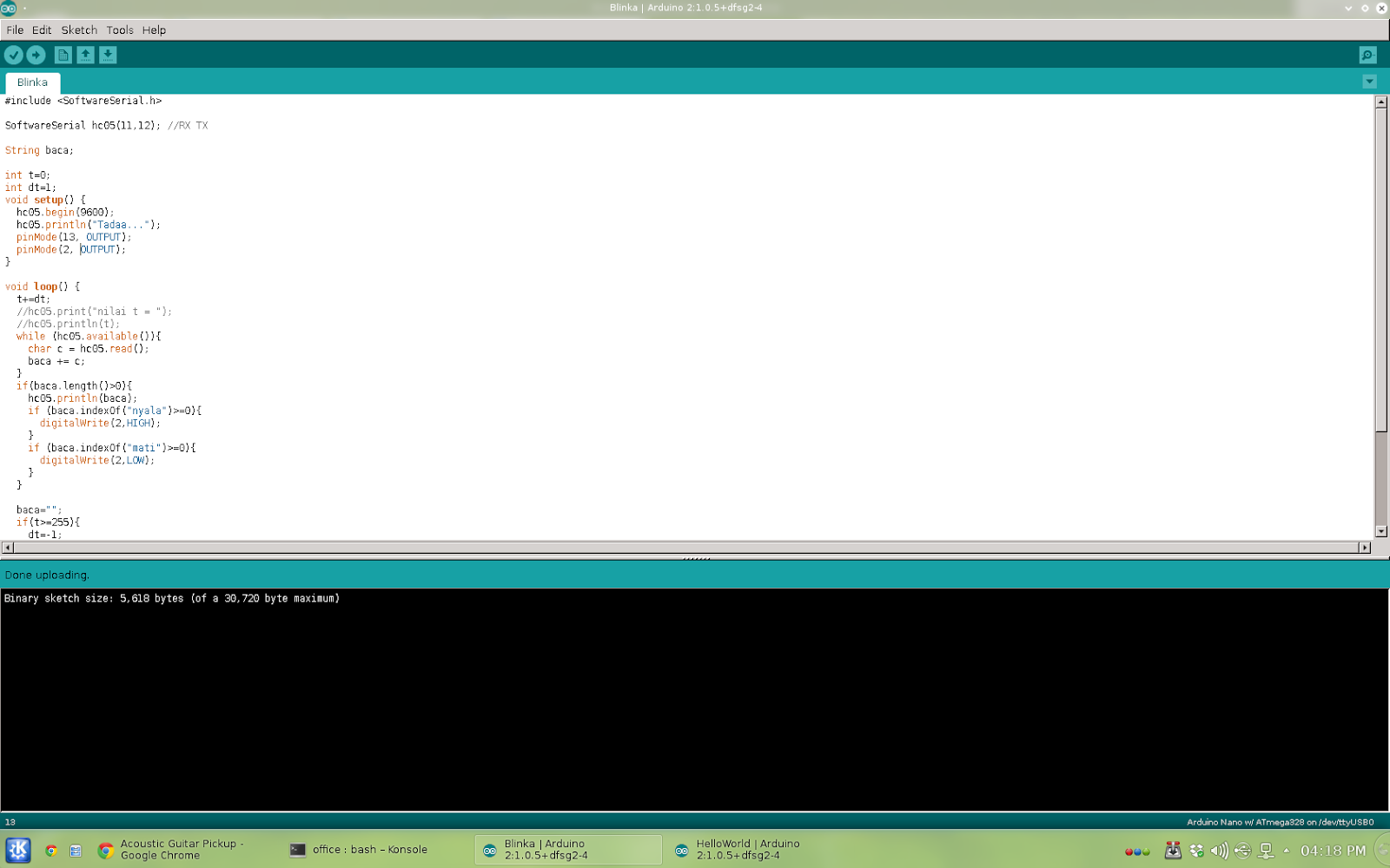
SoftwareSerial hc05(11,12); //RX TX

String baca;

int t=0;
int dt=1;
void setup() {
  hc05.begin(9600);
  hc05.println("Tadaa...");
  pinMode(13, OUTPUT);
  pinMode(2, OUTPUT);
}

void loop() {
  t+=dt;
  //hc05.print("nilai t = ");
  //hc05.println(t);
  while (hc05.available()){
    char c = hc05.read();
    baca += c;
  }
  if(baca.length()>0){
    hc05.println(baca);
    if (baca.indexOf("nyala")>=0){
      digitalWrite(2,HIGH);
    }
    if (baca.indexOf("mati")>=0){
      digitalWrite(2,LOW);
    }
  }

  baca="";
  if(t>=255){
    dt=-1;
    digitalWrite(13, LOW);
  }
  if(t<=0){
    dt=1;
    digitalWrite(13,HIGH);
  }
  analogWrite(3,t);
  delay(27);
  }


unsigned long t0 = 0;
const long dt = 1000;
void blinkNoD(int pin) {
  unsigned long t = millis();
  if(t - t0 >= dt) {
    t0 = t;
    led=!led;
    digitalWrite(pin, led);
  }
}
unsigned long t0 = 0;It turned out that my analogRead instability is another problem, get to work on it, :)
const long dt = 1;
void blinkNoD(int pin) {
t0 += dt
if(t0 >= 4) {
t0 = 0;
led=!led;
digitalWrite(pin, led);
}
}

My sky is high, blue, bright and silent.

Nugroho's (almost like junk) blog
By: Nugroho Adi Pramono

