SoftwareSerial mySerial(8, 9); // RX, TX
int t=1;
int i=1;
LiquidCrystal lcd(12, 11, 5, 4, 3, 2);//rs e d4 d5 d6 d7
String tulisan = "Tadaa..., heheh...., hihihi :)";
String info =":)";
void setup() {
  pinMode(7,INPUT);
  pinMode(6,OUTPUT);
  pinMode(10,OUTPUT);
  pinMode(13,OUTPUT);
  lcd.begin(16, 2);
  lcd.print(tulisan);
  mySerial.begin(9600);
  delay(1000);
}


void loop() {
  //lcd.clear();
  if (digitalRead(7)==1){
    digitalWrite(10,HIGH);
  }else{
    digitalWrite(10,LOW);
  }
  if (mySerial.available()){
    digitalWrite(13,HIGH);
    while(mySerial.available()>0){
      tulisan=mySerial.readString();
      mySerial.println(tulisan);
    }
  }
  lcd.setCursor(1,0);
  lcd.print(tulisan);
  //scroll first row if text length's beyond 16
  int l= tulisan.length()-12;
  info ="P7=";
  info+=digitalRead(7);
  info+=",l=";
  info+=tulisan.length();
  lcd.setCursor(t,1);
  lcd.print(info);
  digitalWrite(13,LOW);
  lcd.scrollDisplayLeft();
  t++;
  if (t>=l){
    t=1;
    lcd.clear();
  }
  delay(1000);
}
//PWM: 3, 5, 6, 9, 10, and 11
.
Agar output LCD hanya bagian atas saja yang scroll sedangkan yang baris kedua tetap diam.
Triknya adalah memberi LCD perintah scroll seperti biasa di arduino namun kita mengupdate posisi kursor di baris kedua agar tulisan selalu nampak di layar (dalam hal ini adalah string bernama 'info')
In addition of my previous tinkering with LCD on arduino nano, I add a chunk of program to display the state of digital pin 7 on second row LCD.
I also remove the scroll command, package it as separate function but not called. I plan to using another scrolling method, some code without delay. (had it in mind, but still lazy to coding it, maybe next)
void scLeft(){ for (int i = 0; i < tulisan.length(); i++) { lcd.scrollDisplayLeft(); delay(150); } }
void scRight(){ for (int i = 0; i < (tulisan.length()+16); i++) { lcd.scrollDisplayRight(); delay(150); } }
void scDef(){ for (int i = 0; i < 16; i++) { lcd.scrollDisplayLeft(); delay(150); } } //PWM: 3, 5, 6, 9, 10, and 11
.
Menulis perintah ke baris pertama LCD via bluetooth, baris kedua digunakan untuk mengecek pin 7 (digital). Fitur scrill (di post sebelumnya dihilangkan, ada di bawah sebagai function tetapi tak dipanggil di program utama)
void loop() { if (Serial.available()){ lcd.clear(); while(Serial.available()>0){ tulisan=Serial.readString(); lcd.print(tulisan); } } // scroll 13 positions (string length) to the left // to move it offscreen left: for (int i = 0; i < tulisan.length(); i++) { // scroll one position left: lcd.scrollDisplayLeft(); // wait a bit: delay(150); }
// scroll 29 positions (string length + display length) to the right // to move it offscreen right: for (int i = 0; i < (tulisan.length()+16); i++) { // scroll one position right: lcd.scrollDisplayRight(); // wait a bit: delay(150); }
// scroll 16 positions (display length + string length) to the left // to move it back to center: for (int i = 0; i < 16; i++) { // scroll one position left: lcd.scrollDisplayLeft(); // wait a bit: delay(150); }
// delay at the end of the full loop: delay(1000);
}
.
Menampilkan dan men-scroll text yang diketik menggunakan monitor serial di arduino nano.
Tantangannya adalah membaca serial data dan menyimpannya sebagai string. Di versi lama, kita harus membaca komunikai serial sebagai char yang tentu saja sangat merepotkan. Untungnya kita mempunyai perintah readString, :)
After subconsciously try it on my debian machine about a week, now when I have a chance to write on arduino IDE on my Macbook, it wont upload the sketch, no port for nano.
installing FTDI driver didn't help because it use CH340G chip for com.
Grab the driver from http://www.wch.cn/downloads.php?name=pro&proid=178
Menyalakan LED 3 dengan mode PWM dengan perintah analogRead, sehingga nyala LED berangsur-angsur dari redup ke terang ke redup lagi (255 tingkat kecerahan).
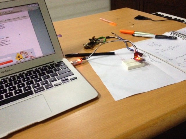
Menyalakan LED 2 dengan perintah melalui port serial bluetooth dari Mac OS X.
(program ditulis dan dijalankan di linux Debian)
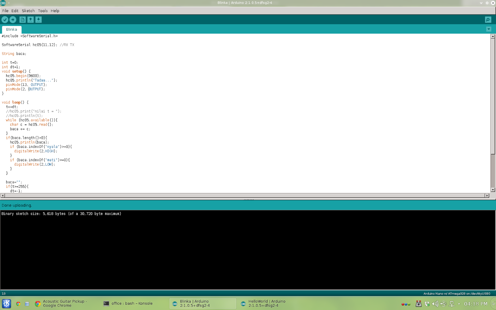
led pin 3 dapat dinyalakan (setelah microcontroler tersambung dengan komputer via bluetooth) dengan mengetikkan 'nyala' atau 'mati' pada konsole di komputer.
#include <softwareserial .h>
SoftwareSerial hc05(11,12); //RX TX
String baca;
int t=0; int dt=1; void setup() { hc05.begin(9600); hc05.println("Tadaa..."); pinMode(13, OUTPUT); pinMode(2, OUTPUT); }
void loop() { t+=dt; //hc05.print("nilai t = "); //hc05.println(t); while (hc05.available()){ char c = hc05.read(); baca += c; } if(baca.length()>0){ hc05.println(baca); if (baca.indexOf("nyala")>=0){ digitalWrite(2,HIGH); } if (baca.indexOf("mati")>=0){ digitalWrite(2,LOW); } }
We could write code in it, connecting parts on breadboard (or project-board), auto-route it to schematic and pcb layout (single or double layer).
It has several arduino board ready on parts section
Dengan Fritzing, kita bisa menulis kode mikrocontroler di sini, memasang komponen dan menyambung dengan kabel di project-board, kemudian me-route secara otomatis menjadi skematik seperti di EWB (Electronic Work Bench), routing otomahis juga dilakukan untuk menghasilkan layout PCB seperti di Protel (mendukung single dan double-layer)
Well, not for all, but for me it becomes problem while turning led on using analogWrite command, some led just won’t completely shut down.
(Maybe it completely unrelated, but my analog reading on A0 is oscillating, very unstable)
I have the commands packed on a function
unsigned long t0 = 0;
const long dt = 1000;
void blinkNoD(int pin) {
  unsigned long t = millis();
  if(t - t0 >= dt) {
    t0 = t;
    led=!led;
    digitalWrite(pin, led);
  }
}
Since I already have delay in loop, and it really messed with the timing (not mention that maybe the analog reading instability have anything to do with it), I decided to modify the blink code, still without delay command.
KProgram ini digunakan untuk melihat nilai sensor (berupa tegangan) di port analog 0 (A0) di ATMega328.
Di sini sensor diwakili oleh potensiometer yang kaki tepinya masing-masing dihubungkan ke vcc dan ground, kaki tengah dihubungkan ke port analog 0.
Microcontroler membaca port analog 0 yang nilainya kemudian dikirimkan secara serial via bluetooth, juga untuk menyalakan empat led sesuai dengan nilai pembacaan sensor.
Karena ATMega328 memliliki resolusi pembacaan analog sebesar 10-bit, maka led diset sedemikian sehingga led 1 menyala jika nilai kurang dari 255, led 1 dan 2 menyala jika nilai sensor antara 255 dan 512, dst.
Sebagai tambahan, perintah yang digunakan untuk menyalakan led adalah analogWrite() bukan digitalWrite() sehingga meski nilai sensor kurang dari 255, kita masih bisa membedakan levelnya dengan tingkat redup-terangnya led pertama (0 mati, 50 redup, 255 nyala terang).
I also use it to blink led without delay, fade without delay, write to serial via Bluetooth module (HC-05) AND USB-to-TTL.
Notice that I have two TX and two RX, the default pin (0 and 1) for usb communication (upload sketch and debugging), the software serial TX,RX (pin 8 and 7) is used for bluetooth communication.
Here the code. I use some function to isolate some group of commands for easy debugging.
#include <softwareserial .h>
SoftwareSerial mySerial(8, 7); // RX, TX
int led = LOW; int dterang = 5; int terang = 11; unsigned long t0 = 0; const long dt = 1000;
Got HC05 Bluetooth Module last Saturday at electronic store, connect it with my Arduino Pro Mini (ATMega 328 based) the usual way: tx—rx, rx—tx, vcc—5v and ground—0v. Powered it on alongside the Pro Mini. The led indicator blinked, good sign, :)
Pairing with my Mac is easy, but make sure the pairing code is 1234, mac use 0000 as default code. If paired successfully the led blink pattern will change.
Open the serial monitor and, nothing appeared, :(
Maybe the IDE busy so I open the OS X terminal and access using screen:
$screen /dev/cu.HC-05-DevB
Still nothing happened.
Unplug all the cable, plug it again. And yup, there’s serial output (using Arduino IDE serial monitor or screen command on terminal )
I have a Mac with Yosemite.
Apparently, most of my problem with arduino board is loose cable connection, :)
I saw it at electronic part shop while shopping for my DIY guitar preamp part. It based in ATMega 328 and it waking up my years-sleeping microcontroller spirit :D
I always love assembly language, I have several project on ATMega based microcontroller as programmer but it's just that. I just love programming without bothered by hardware, minsys or whatnot.
It's true that arduino language is not asm; it's simplified C. But it come in package, I just have to program it and it'll work. It's the closest thing I got to hardware related interface, for now (I still have a plan that some day I'll master both microcontroller hardware and software interfacing :) )
Anyway, I bought this Arduino Pro Mini and an USB to TTL module.
It just my luck that I bought that PL2303HX module and not Sparkfun breakout board or FTDI connector as my Arduino Pro Mini layout is totally different; it has same dimension as original but the hole for pins is different (it has more hole than the original). The breakout board probably won't match and maybe useless (I don't konw about FTDI). So I think the pl2303hx usb to ttl usb-stc-isp is my best shot.
My luck, or probably not, it means my Arduino Pro mini is the clone, :)
I download Arduino IDE for my MacBook Air with OS X Yosemite.
Install it, there's no problem as I changed my macbook setting on software installer permission (set to ANY)
Ran the IDE, use the example code, blinking LED.
compile it, OK
Upload it, this error message appear:
Arduino: 1.6.2 (Mac OS X), Board: "Arduino Pro or Pro Mini, ATmega328 (5V, 16 MHz)"
Sketch uses 1,068 bytes (3%) of program storage space. Maximum is 30,720 bytes.
Global variables use 11 bytes (0%) of dynamic memory, leaving 2,037 bytes for local variables. Maximum is 2,048 bytes.
avrdude: stk500_recv(): programmer is not responding
avrdude: stk500_getsync() attempt 1 of 10: not in sync: resp=0x00
avrdude: stk500_recv(): programmer is not responding
avrdude: stk500_getsync() attempt 2 of 10: not in sync: resp=0x00
avrdude: stk500_recv(): programmer is not responding
avrdude: stk500_getsync() attempt 3 of 10: not in sync: resp=0x00
avrdude: stk500_recv(): programmer is not responding
avrdude: stk500_getsync() attempt 4 of 10: not in sync: resp=0x00
avrdude: stk500_recv(): programmer is not responding
avrdude: stk500_getsync() attempt 5 of 10: not in sync: resp=0x00
avrdude: stk500_recv(): programmer is not responding
avrdude: stk500_getsync() attempt 6 of 10: not in sync: resp=0x00
avrdude: stk500_recv(): programmer is not responding
avrdude: stk500_getsync() attempt 7 of 10: not in sync: resp=0x00
avrdude: stk500_getsync() attempt 8 of 10: not in sync: resp=0x00
avrdude: stk500_recv(): programmer is not responding
avrdude: stk500_getsync() attempt 9 of 10: not in sync: resp=0x00
avrdude: stk500_recv(): programmer is not responding
avrdude: stk500_getsync() attempt 10 of 10: not in sync: resp=0x00
Install FTDI drivers, not work, obviously because I don't use it.8
try it in my Linux Debian machine (after install it via sudo apt-get install arduino command), success
back to mac, success too, strange
After several success and error upload, it turned out that my tx rx connection is not thigh enough, heheh...
The pictures below made after I secure the connection by permanently solder it. Not my actual plan because initially I prefer it in plug and play form.
Some note
Make sure that PL2303HX and Arduino have this connection right
Vcc to 5V
GND to GND
TX to RX
RX to TX
Before clicking upload button on IDE, we have to press and hold reset button on Arduino board and release about one second after it (or after console displaying message: 'sketch size...').
I've found new kind of error like this
Arduino: 1.6.2 (Mac OS X), Board: "Arduino Pro or Pro Mini, ATmega328 (5V, 16 MHz)"
Sketch uses 4,480 bytes (14%) of program storage space. Maximum is 30,720 bytes.
Global variables use 216 bytes (10%) of dynamic memory, leaving 1,832 bytes for local variables. Maximum is 2,048 bytes.
avrdude: ser_open(): can't open device "/dev/cu.usbserial": Resource busy
ioctl("TIOCMGET"): Inappropriate ioctl for device
Problem uploading to board. See http://www.arduino.cc/en/Guide/Troubleshooting#upload for suggestions.
This report would have more information with
"Show verbose output during compilation"
enabled in File > Preferences.
It happened when I open serial monitor using Terminal apps on OS X and trying to upload the sketch while it running command
$ screen /dev/cu.usbserial
or
$screen /dev/cu.HC-05-DevB
We have to close it first (not just detach) using command
My string acoustic-electric guitar is borrowed and not back, leave my classic nylon string Yamaha guitar and an Ibanez clone with is by itself stand at the opposite pole of my need (rock/metal amplified sound or warm natural classic).
I need something between that and decide to install piezo on my classic nylon string. It pretty straightforward, just need few minutes. The problem is when i plugged it on my amp, it has almost no sound. I have to crank the volume knob all the way up to hear 'normal' level volume. It need pre-amplifier.
I uninstalled the piezzo (what I'm thinking at that moment, :D ) and using my Ibanez clone as testing guitar, with normal jack and all.
here the schematic
It Occured to me that this Pre-Amp could act as Distortion effect if we set the gain super high. I do it by add a resistor parallel to 100k. And the sound is suddenly very different. It's very clipped and distorted yet there's something missing (for me). I like soft clipping. So I plan to tinkering with some resistor value or add potentiometer to it
If we don't want distortion, just louder gain, we could always using two stage preamp (I don't know the proper name of it)